 Electromagnetic water meter
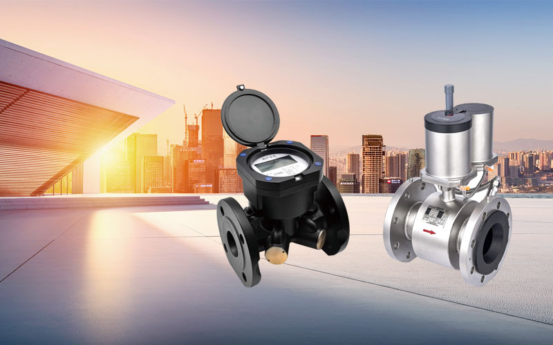
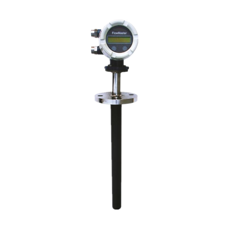
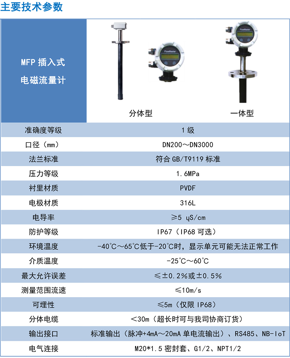
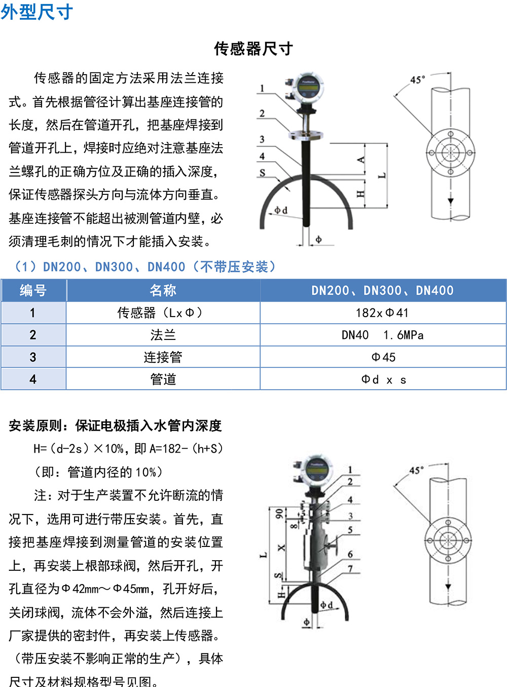
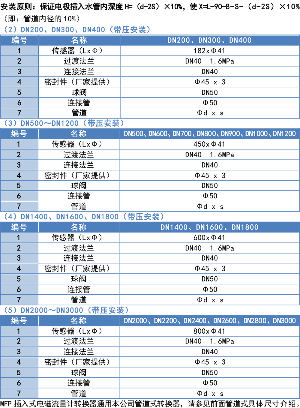
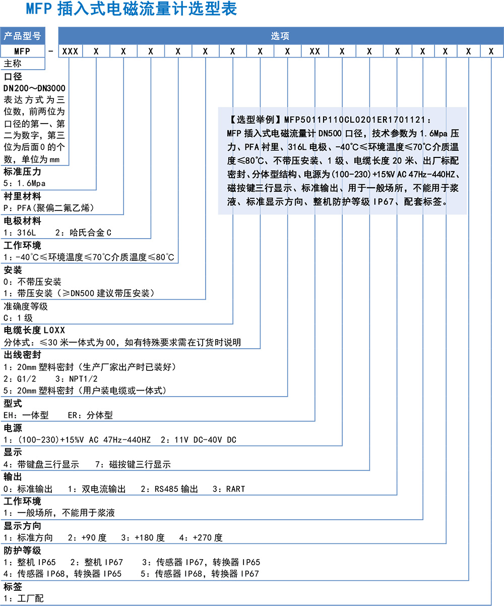
MFP insertion type electromagnetic flowmeter is a new type of fluid flow meter developed on the basis of pipeline electromagnetic flowmeter. It retains the advantages of pipeline electromagnetic flowmeter on the basis of pipeline electromagnetic flowmeter installation difficulties in large pipelines, large costs and other shortcomings, according to NIKURADS (NIKURADS) principle, electromagnetic method by measuring the average flow rate of the fluid, so as to obtain the volume flow of the fluid. In particular, the use of openings with pressure, pressure installation technology, insertion type electromagnetic flowmeter can be installed without stopping (water), but also in the cast iron pipeline, cement pipeline installation. Insertion type electromagnetic flowmeter development success, for the detection of fluid flow provides a new means.
With the general electromagnetic flowmeter is different, inserted electromagnetic flowmeter sensor is the outer side of the formation of the external emission of magnetic fields, measuring electrodes at the end of the sensor or on both sides of the electromagnetic flowmeter as shown in the figure below principle. It is worth noting that the sensing signal of the outer emitting magnetic field electromagnetic flow rate sensor is affected by the thickness of the boundary layer between the fluid and the magnetic field, which will reduce the linearity of the measurement. For
MFP insertion electromagnetic flowmeter, the conductive fluid in the pipeline is a conductor moving in the magnetic field, the distance between the two electrodes is the conductor length L.
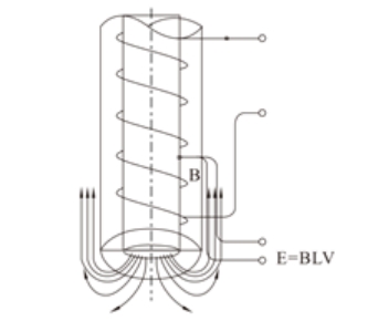
Its induced voltage is proportional to the average flow rate. At this point the fluid flow in the pipe can be derived from this:
equation (1)
Q=πD²U/4KBL
D: measuring pipe diameter U: induced voltage
B: magnetic induction strength K: coefficient related to the magnetic field distribution